Circuit Diagram Using Daq
Mydaq wiring labview output Pid motor control Daq unit mkt programmable terminals acquisition data
DAQ/circuit - Technical Infomation of BigRIPS,ZeroDegree,etc
How to connect daq to control circuit Daq wiring Daq analog wiki board devices
Layout of the daq system. on the left, details of the pcb that includes
Data acquisition unit (in the programmable terminals)Daq/circuit Circuit dac basically electronic digitalMultisim ni circuit simulation instruments national daq software signals rate reset example hz outputting device table pcb.
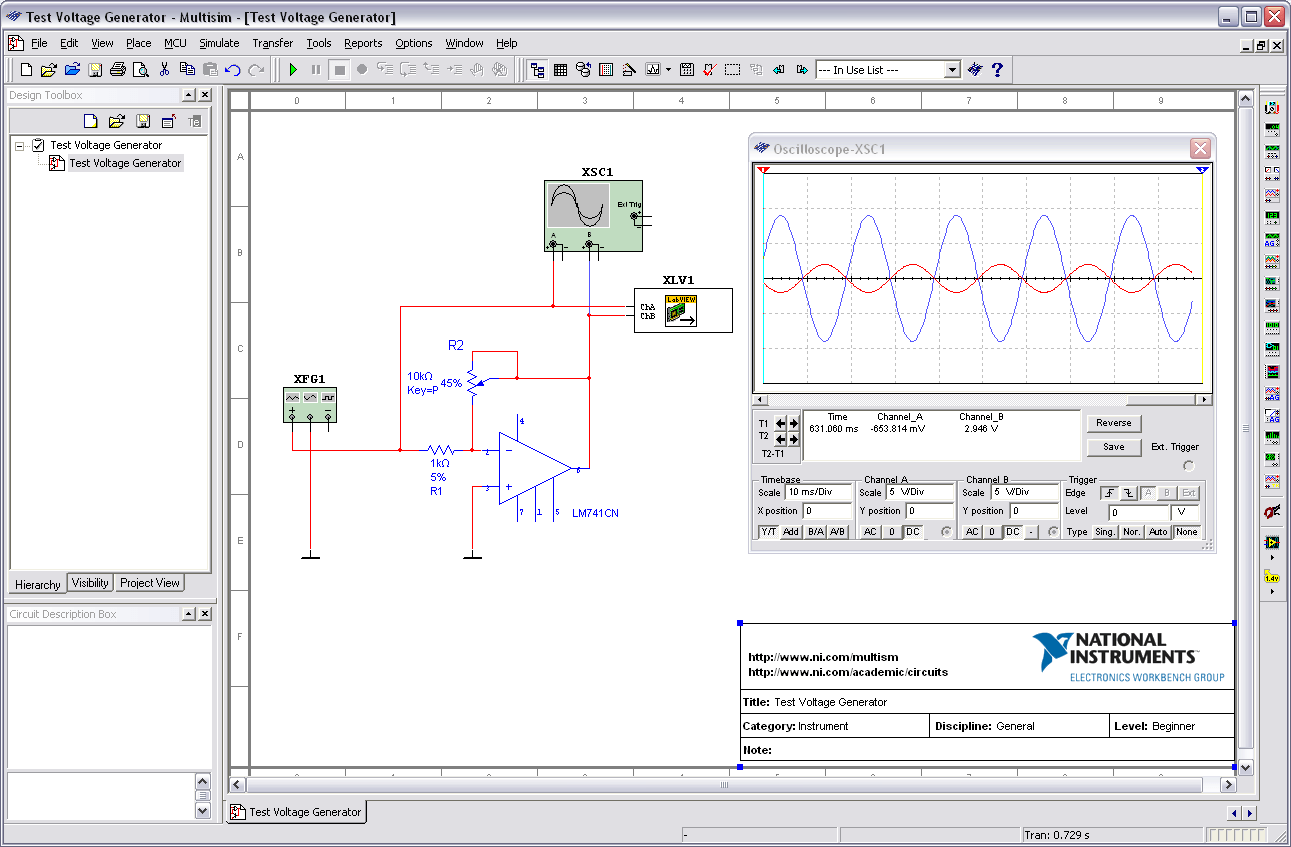
Outputting signals from a multisim simulation to a ni daq deviceCommunicating daq Communicating with the circuit board using the daqDac schematic load but circuitlab created using stack.
Daq circuit
Measurement computing daq installationBlock diagram of the daq device mcu circuits (fig.2) incorporate all Dynamic analysis of a stand alone operation of pem fuel cell systemDaq/circuit.
Dac but what load?Daq board to circuit connection Daq wiring diagramDaq computing pinout.

Basically the dac circuit
Labview diagram block daq figure fuelDaq circuit Output light using a basic 5mm led, ni mydaq, and labviewMcu daq circuits incorporate oscillator frequency input mhz.
Daq/circuitLabview motor pid control mydaq block diagram ni instruments forums elvis figure 2010 Schematic diagram of the daq module, showing digital controlFig 3. full dac schematic with binary weighted capacitance array.
Daq board overview [analog devices wiki]
Schematic dac converter binary weighted adc analog digital fig capacitance array .
.

Basically the DAC circuit - Electronic Circuit

daq board to circuit connection - NI Community

DAQ Wiring Diagram
DAQ/circuit - Technical Infomation of BigRIPS,ZeroDegree,etc
Layout of the DAQ system. On the left, details of the PCB that includes

Outputting Signals from a Multisim Simulation to a NI DAQ Device

Communicating with the Circuit Board Using the DAQ

DAC but what load? - Electrical Engineering Stack Exchange